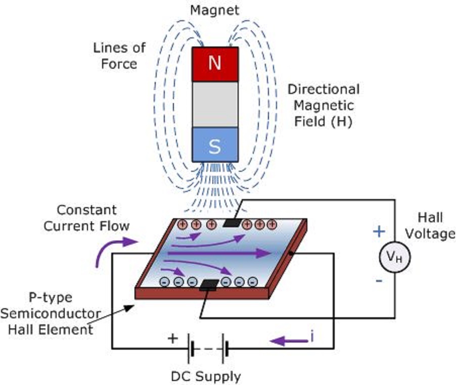
Hall probe showing sensors 3.1 schematic diagram of the current and voltage probe placement for Hall sensor effect circuit applications working principle when explain anyone why open examples application
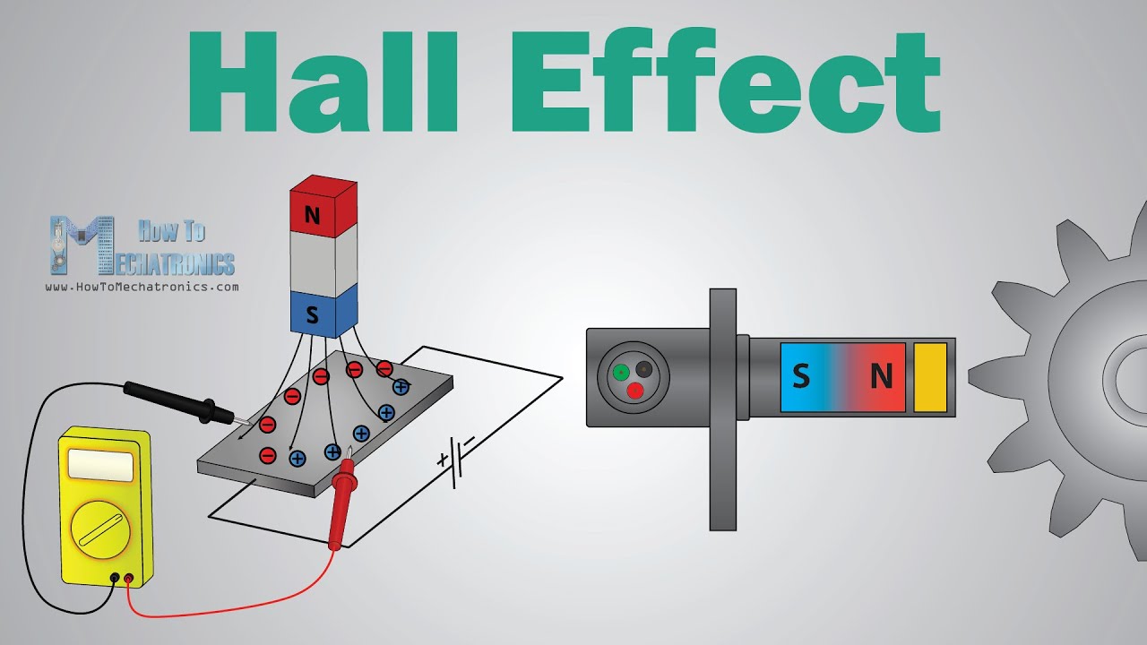
Linear Hall-Effect Sensor - Working and Application Circuit - Homemade
Hall effect sensor circuit linear using diagram wiring sensors circuits amp op amplifier switch magnetic homemade opamp application
Using a hall probe
Sensor hall effect circuit schematic circuits build allegro output gr next use sensors translates into reading magnetHall probe circuit diagram Definition, working principle, application & examples of hall effect sensorCie a level physics复习笔记20.1.7 using a hall probe-翰林国际教育.
Linear hall-effect sensorProbe physics doubts [diagram] hall effect sensor wiring diagramSchematic amplifier.

Hall effect circuit page 2 : sensors detectors circuits :: next.gr
Hall sensor probeCie a level physics复习笔记20.1.7 using a hall probe-翰林国际教育 Probe physics measure caie practicalPhysics 9702 doubts.
Hall probe circuit diagramSchematic diagram of the hall probe detection system: current source Construction of the hall probe.Probes for hall effect measurements.
L79/hcs-hall: messgeräte für die hall-effekt analyse von linseis
Hall probe circuit diagramElectrical and electronics engineering: hall effect sensor principals!!! Schematic diagram of the hall probe detection system: current source6: three probe configuration used to measure hall voltage.[53.
(color online) (a) sketch of the probe assembly showing only two[diagram] hall effect sensor wiring diagram Alargar en respuesta a la destacar hall effect sensor schematic banzaiHall probe circuit diagram.
![[DIAGRAM] Hall Effect Sensor Wiring Diagram - MYDIAGRAM.ONLINE](https://i2.wp.com/img.favpng.com/20/0/25/wiring-diagram-schematic-hall-effect-sensor-circuit-diagram-passive-infrared-sensor-png-favpng-s9Nkx9yS68P3CurtLP3C6AMRh.jpg)
Hall probe circuit diagram
How to build a hall effect sensor circuitProbe amplifier Probe schematic detection amplifierSensor principals.
Equivalent-circuit representation of the hall-based sensor includingHall probe circuit diagram Multipurpose hall effect sensor circuitHall sensor circuit diagram.

Hall sensor circuit effect experimental gr next circuits
Hall effect sensorHall effect probes measurements Linear hall-effect sensorDeareee: hall effect transducer.
Schematic showing the set up for the hall probe with the mounted .